MHDCT Details
This section gives a detailed account of incorporating MHDCT into your simulation. Please read the overview in MHD Methods first. Also, read the implementation method paper, Collins et al 2010.
Parameter Compatibility
Due to the consistency requirements of MHDCT, several parameter combinations can and will fail in hilarious ways. Defaults have been selected to give the best performance and the consistent results. The minimum set of parameters to be enabled in your new parameter file are
NumberOfGhostZones = 5
HydroMethod = 6
Other parameters must always be set, and sometimes are set differently in other parameter files:
FluxCorrection = 1
CorrectParentBoundaryFluxes = 1
Initialization
If you have an initializer that you wish to add MHDCT to, several things
need to be done:
1.) Set Labels and Units Define the labels in the primary problem initializer, e. g. MHDBlastInitialize.C.
Use the function MHDCTSetupFieldLabels();
2.) Note: if your main initializer uses a call to InitializeUniformGrid, you can skip steps 2 and 3.
In the grid initializer, e.g. Grid_MHDBlastInitializeGrid.C, add
BaryonField pointers for the centered magnetic field. Code should look like
if( UseMHD ){
  FieldType[NumberOfBaryonFields++] = Bfield1;
  FieldType[NumberOfBaryonFields++] = Bfield2;
  FieldType[NumberOfBaryonFields++] = Bfield3;
}
if( HydroMethod == MHD_RK ){
  FieldType[NumberOfBaryonFields++] = PhiField;
}
This is the same as Dedner simulation. Old versions of the code used a variable CenteredB, which was redundant and cumbersome.
3.) Allocate the appropriate fields
Ensure your code calls this->AllocateGrids(); rather than
BaryonField[field] = new float[size].
4.) Fill the Fields This can be either very straight forward, or very difficult depending on your problem. Here we’ll present three cases. Note that the very most important thing is that the field is numerically divergence free.
4a) Uniform Magnetic Fields If you have a uniform magnetic field defined by UniformField[3], you can initialize them like this:
for ( int field=0; field < 3; field++ ){
  for ( int i=0; i<MagneticSize[field]; i++ ){
    MagneticField[field][i] = UniformField[field];
  }

}
Here, MagneticSize[] is defined in grid::AllocateGrids. In some initializers this is done within the i,j,k loop
over BaryonField. This is also acceptable, the missing face will be taken care of by the boundary set on the root grid.
4b) Simple Analytic Function If you have a function, Function, that is numerically
divergence free but a function of space, you can loop over the grids
zone-by-zone in the following manner. NOTE that your function is probably not
like this Many functions are analytically divergence free, but numerically
they are not. Piecewise constant functions are possible candidates, anything
involving sine is not.
for ( int field=0; field < 3; field++ ){
  for ( k=0; k<MagneticDims[field][2]; k++ ){
    for( j=0; j<MagneticDims[field][1]; j++ ){
      for( i=0; i<MagneticDims[field][0]; i++ ){
        index = i + MagneticDims[field][0]*(j + MagneticDims[field][1] * k);
        MagneticField[ field][ index] = Function(i,j,k);
      }
    }
  }
}
4c) Anything Else For any function that is more complex than a Heaviside
function, you will need to write your initial magnetic field as the curl of a
vector potential,  . The curl operator,
grid::MHD_Curl, will allow you to take any field you like to initialize the
field. Due to data structure limitations, we use the ElectricField to store
the vector potential in this case. Such code might look like this:
for ( int field=0; field < 3; field++ ){
    for ( k=0; k<ElectricDims[field][2]; k++ ){
      for( j=0; j<ElectricDims[field][1]; j++ ){
        for( i=0; i<ElectricDims[field][0]; i++ ){
          index = i + ElectricDims[field][0]*(j + ElectricDims[field][1] * k);
          ElectricField[ field ][ index] = Function(field,i,j,k);
        }
      }
    }
  }
  this->MHD_Curl(GridStartIndex, GridEndIndex, 0)
where Function is anything you like.
5.) Center the magnetic field The final step is to fill the centered field, BaryonField[B1Num] (etc) from MagneticField. Call this
function once you’ve filled MagneticField.
this->CenterMagneticField();
6.) Add to the Energy Finally you need to add the magnetic energy to the total energy. There are several ways to accomplish this. Something like this is sufficient:
int DensNum, GENum, Vel1Num, Vel2Num, Vel3Num, TENum, B1Num, B2Num, B3Num;
this->IdentifyPhysicalQuantities(DensNum, GENum, Vel1Num, Vel2Num, Vel3Num,
                                 TENum, B1Num, B2Num, B3Num);
for( i=0; i<size; i++ ){
  BaryonField[ TENum][i] += 0.5*(BaryonField[B1Num][i]*BaryonField[B1Num][i]+
                                 BaryonField[B2Num][i]*BaryonField[B2Num][i]+
                                 BaryonField[B3Num][i]*BaryonField[B3Num][i])/BaryonField[ DensNum][i];
}
7.) If you refine on initialization Some problems refine on initialization.
If you have such an initializer, quite often the grid initializer is called on
successive levels, then projected from fine to coarse. If your routine does
this, AND you have a simple (i.e. you didn’t call MHD_Curl) initializer,
you can force the magnetic field to be projected by setting
MHD_ProjectB=TRUE;
MHD_ProjectE=FALSE;
before the projection is done. It is imperative that it gets set back after the projection with
MHD_ProjectB=FALSE;
MHD_ProjectE=TRUE;
or the code will fail horribly.
If you refine on initialization and have a complex initializer you will need to project the electric field, then take the curl over the whole grid. I have never done this, so writing documentation would be speculative at best. Please feel free to contact David Collins through the Enzo mailing list in such a case, and I can both help make it happen and write the document.
Data Structures
Enzo uses two representations of the magnetic field, one located at the center
of the zone and one at the face. The centered field is stored in
BaryonField, and will use identical code to the field with the Dedner
solver.
The staggered magnetic field is stored in MagneticField, and electric field, ElectricField, is
centered on the zone edges. MagneticField, being stored on the faces of the
zones, has one additional point along each component. For instance, if a grid had dimensions  then
then
 will have dimensions
 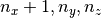 .
. ElectricField has additional points transverse to the direction
of the component, so  has dimensions
 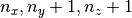 .
There are several helper variables, such as
.
There are several helper variables, such as MagneticDims[3][3],
ElectricDims[3][3], MagneticSize[3], and ElectricSize[3] to describe
these variables.
The centered magnetic field will be updated by grid::CenterMagneticField()
used strategically throughout the code.
Note that old versions of the code incorporate an additional data structure,
CenteredB, to store the cell centered field. This has been removed, and
should be replaced by BaryonField[B1Num], etc.
For MHDCT, the magnetic field stored in BaryonField
should be considered a read-only quantity– it is
replaced with a centered spatial average of MagneticField as necessary by
the routine CenterMagneticField.
MagneticField should only be modified in a manner that is definitely
divergence free. For more general initialization, one can use the function MHD_Curl
for fields that can be represented by a vector potential.
Interpolation
Interpolation must be done in a divergence-free manner. Balsara
2001 describes this method. Interpolation is done on all three components of
MagneticField at once. This method only allows RefineBy = 2.
One challenge of this method is that newly interpolated regions require
knowledge of any fine-grid data at the same level that may share a face. Thus
instead of simply interpolating from parent grids, then copying from old fine
grids, MHDCT must use the magnetic information from the old fine grids. This is
done by first computing interpolation derivatives (done in Grid_MHD_CID.C
and stored in DyBx, etc) then communicating this information to the relevant
parent grids (done in Grid_SendOldFineGrids.C) This makes MHD-CT
interpolation a 3 grid interaction (Parent, Child, Old Child) rather than a 2
body interaction (Parent and Child) as all other fields.
Projection and Flux Correction
As with other quantities, magnetic fields need to be projected to parents, then
coarse zones next to projected zones need to be corrected to ensure
conservation. As described by Balsara 2001, this involves area weighted
projection of face centered field on the fine grid, then a correction using the
electric field. In order to simplify the logic and machinery, Enzo MHD-CT
actually projects the ElectricField, then takes the curl over the new
magnetic field. This is formally equivalent to projection plus flux correction,
but doesn’t have as many cases to check and grid interactions to worry about.
This is done in EvolveLevel by the routine Grid_MHD_UpdateMagneticField